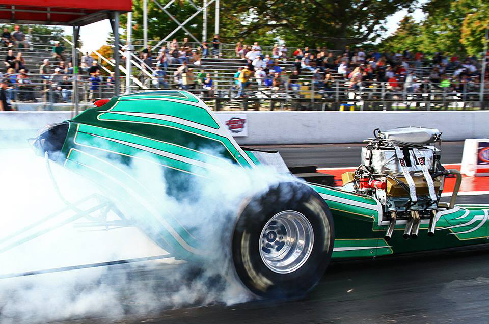
1949 Chevrolet Gasser – Progress 2016 01 16
Click the picture to enlarge the image
We have reunited the Car Nuts Gang once again. The Fourth meeting of the Car Nuts on 01/16/2016 was attended by Anne Lever, Arthur Lever, Jim Boehly, Ken Long, and Lee Bracey.
That has been a lot of progress considering the few times we have been together. That is not to say that there is a LONG way to go.
First project was to create a rear transmission mount where none existed.
Second task was to move the spring perches. This was required because the weight of the new engine caused the spring shackles to flip up.
 |
The original rear transmission mount was removed when the new inner chassis structure was added by Arthur Lever to accommodate the rear four bar setup. |
 |
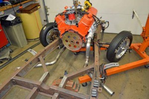
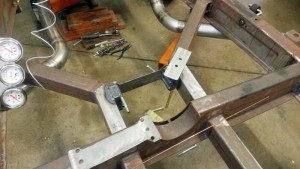
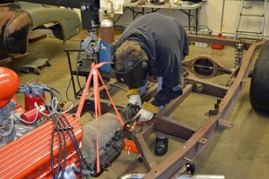
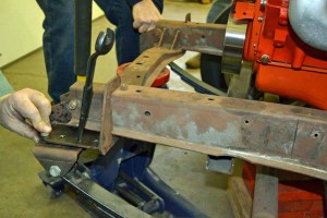
First step was to get the frame where we wanted it (front end still raised for that Gasser look) and then set the angle of the carburetor so that the fuel bowls will sit level. The rear of the transmission was blocked up so that measurements could be taken |
 |
A better mind than mine put his thinking cap on and came up with a design to hold the transmission in place. |
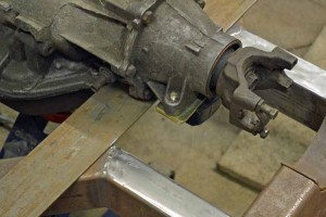 |
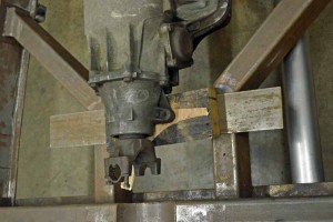
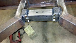
The transmission isolater was bolted to the tail shaft of the transmission |
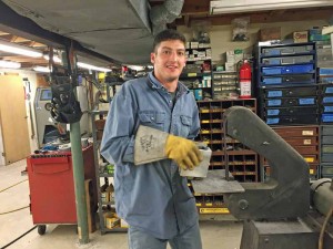 |
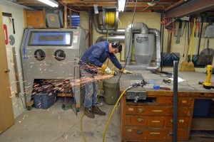
The master fabricator spent some time in the basement creating the work of art that was to become the structure for the rear transmission mount. |
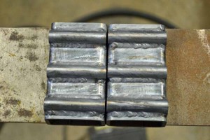
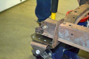
The frame mounts, which will provide adjustability, were created, and welded to the frame rails
 |
 |
 |
Back to the basement to create more grindings for the maintenance crew to clean up. |
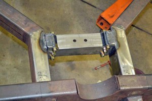
Time to bolt in the sides of the mount to see what we have, and set the top plate in place.
 |
 |
 |
 |
 |
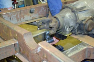
The transmission was set in, bolted in place again and Car Nut member Ken Long tacked the top plate in place. The cross member will now be removed and finish welding will be completed (also it will get powder coated, have to choose a color, have had many suggestions, what is yours?) |
A finished picture of the mount will be added later, I wanted to get this update out and it might be a while before we come back and finish this.
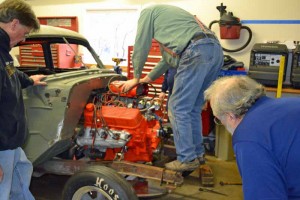
Time to put the body back on again. Needed to do this so that we sure the wheels and tires will end up in the center of the wheel well opening. This meant adding a front fender.
 |
Looking good, now to take it back off so we can work on the spring perches. |
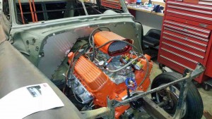 |
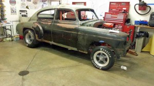
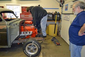
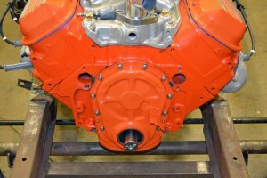
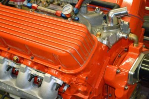
As a side bar, the engine, new fire wall, and fender (don’t miss the new scoop) all together look pretty good! |
We drilled new holes in the front spring perches to move the front axle center line forward to once again center the wheel and tire in the wheel well opening.The other reason was to get the rear spring shackles to uncollapse. This happened when the engine was bolted in.
 |
 |
 |
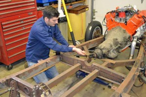
It turns out this guy is good for something after all. He is carrying around all this weight and can now be used to perform a bounce test to see if the rear shackles on the front springs are in a good location to keep them from fold up on themselves. |
 |
Here is the second attempt. This brings back memories of installing the front springs in the El Camino |
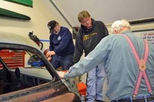 |
Well if one person doing is good then two should be better. The conclusion is we may have to revisit the final location of the front spring perches as we are still able to get them to rotate over center. With the added weight of body panels we may have not yet found the optimum location. |
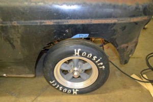 |
We do have the axle center line in the correct location in the wheel well. |
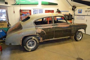 |
In my mind, the stance is just about right. I think the front needs to come up a bit and the rear down a bit and it will be perfect. |
Let me take this opportunity to catch you up on another small project that has been dragging along behind the scenes and I believe we have now completed.
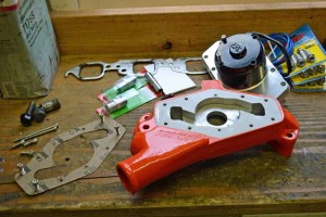
Anyone that has been around me any length of time knows I cannot leave well enough alone. In this case I took a perfectly good stock water pump and threw it away. Purchased an electric pump. That was not good enough so it had to be taken apart and powder coated to match the engine
 |
 |
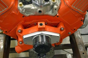 |
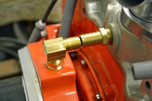
The pump was bolted up and it was discovered that the bypass outlet on the pump, unlike the stock pump, was at a 90 degree angle to the outlet on the intake manifold. On the stock water pump it is angled up to the intake at a 45 degree angle. |
 |
Worse yet is standard fittings were to be used it would guarantee that the connecting hose would kink. I received many suggestions to just plug the holes in the pump and intake. I could not bring myself to do that. |
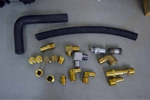 |
Many different ($60.00 worth) (I am crazy after all) fittings were found and purchased. Each trip out of the house we went somewhere different to get different fittings (Home Depot, Lowe’s, Debbie’s Supply, Black Hardware, Power Train, etc) |
Many different combinations were tried, some were closer than others, some so tight the hose would not have been able to be put on.
 |
 |
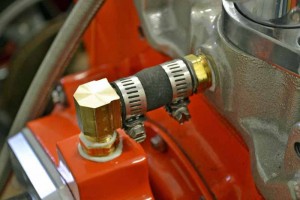 |
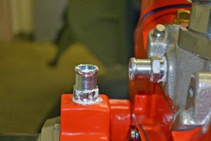
Finally success, a reducer screwed into the pump and then a nipple with a 90 degree bar stock, and then another nipple, a barbed nipple into the intake. The process was to get everything tightened down then turn the fitting in the pump back 30 degrees, put the hose on the intake, and work it onto the pump fitting as it was turned to face the intake. |
There are several other projects that are being worked on, but will hold off on those for now so as not to make these pages to large (firewall, The Scoop, Harmonic balancer)