
ARP Control Module 2017 07 21
Click picture to see larger image
The refrigerator in this RV is going to be brand new except for the box. I replaced the cooling unit last summer that project can be seen here:
Part 1 of 3 on the refrigerator removal and install
Part 2 of 3 on the refrigerator removal and install
Part 3 of 3 on the refrigerator removal and install
The refrigerator keeps perfect temperatures for 24 hours, 35 degrees in the refrigerator and 0 degrees in the freezer when the temperature control is set to 3 on the eye brow refrigerator control panel.
After that, the cabinet on top of the refrigerator starts to get pretty warm to the touch. I do not believe it is the thermistor as the refrigerator keeps such nice temperatures.
The cabinet getting hot turned out to be Caledonia RV service experts installing the wrong vent cap on the roof. The refrigerator was unable to vent correctly. Once the cap was modified (and it will be replaced with a correct new one), the cabinet cooled right down.
I have added a new Dinosaur Control Module.
So what is today’s project? I will add the ARP control on top of the Dinosaur Control Module. ARP Web site https://www.arprv.com/products.php
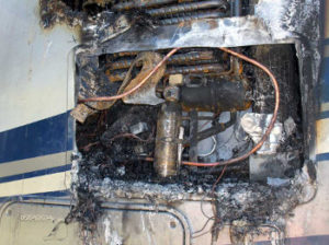 The stated purpose of the ARP module is: “The ARP Control monitors the cooling unit “normal” boiler temperatures. When the cooling unit boiler temperatures rise above the “normal” temperatures, damage to the cooling unit results. Cooling unit damage can lead to premature cooling failure or even worse, the cooling unit boiler can crack due to excessive thermal stress and cause the fluids to leak externally resulting in an RV fire.”
The ARP contact phone number is (406) 494-1959.
I found the web site somewhat confusing and navigation of the web site could be better.
Some of the processes to set different functions up on the unit seem complicated, as an example here are the steps need to reset the fan temperature trip point.
1) Go to set up mode.
_______a) Turn the unit off
_______b) Turn the unit back on
_______c) Hold the right button and momentarily touch the left button
2) Use center button to advance to fan function
3) Press right button to change setting.
4) Press left button to exit adjustment mode (get 0 but not OFF)
5) Use center button to advance to save/store “S–”
6) Hold right button till “STO” appears
7) Turn unit off to exit set up.
8) Turn the unit back on to enter the ARP mode
There are several variations of units you can order. I ordered one of their more complete units in that it contained the fan controller, two fans, and a circuit breaker to protect the unit.
The user and installation manuals do not come with the unit and are found on the ARP web site.
The General Install Guide is at this link https://www.arprv.com/pdf/General_Install_Guide_v3.x.pdf
The User Guide is at this link https://www.arprv.com/pdf/ARP_User-Guide_v3.x.pdf
The Trouble Shooting Guide is at this link https://www.arprv.com/pdf/Troubleshooting_Guide_v3.x.pdf
So let’s get started. Some of these pictures may be familiar as some of the processes need to be repeated from the cooling unit replacement project.
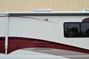
My vent set up is a lower side vent and a roof top vent. Currently, the roof top vent has been spaced up to allow for ventilation, and in addition, the “vanes” in the vent have been trimmed back.
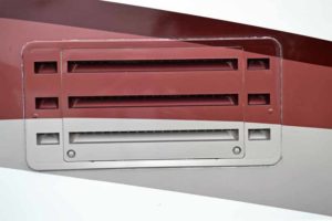
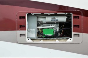
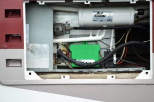
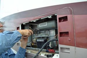
The cover on the side vent is removed to gain access to the guts of the cooling unit for the refrigerator. Note the new Dinosaur Control Module (the green box)
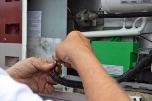
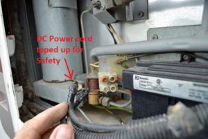
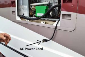
Take the normal safety precautions before removing the refrigerator from the cabinet. Disconnect and tape the ends of the DC power supply, unplug the A/C cord, and turn the propane off at the tank and, if removing the refrigerator, disconnect the propane line from the cooling unit.
Do not forget to turn the propane back on before you test the unit. I kept getting the check light on the refrigerator and then realized I still had the propane shut off.
The reason my DC power cord is so heavy is that DC power for the refrigerator was an option on my Motor Home. I do not have it however.
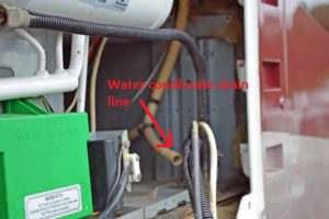
Also disconnect the water condensation line. Some of these just stick through the access cover; mine actually drains under the motor home

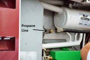
Be sure to use two wrenches when disconnecting the propane line: one to hold the mount and the other on the castle nut on the line. This will save the mount from taking the strain.
So now the propane, AC power, water condensate drain line and the DC power has been disconnected. Time to move inside.
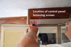
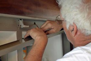
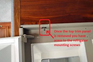
The screws that hold the top of refrigerator in the cabinet are behind the trim panel of the top control panel. Those screws are short machine screws and can be accessed through the holes in the upper hinges. Once the two screws have been removed, the top control panel can be pulled away from the refrigerator and the control wires unplugged from the control circuit board.
The whole panel is now separated from the refrigerator and can be safely stored away.
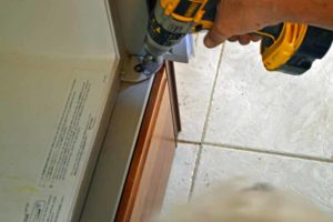
The screws that hold the top of the refrigerator into the cabinet are located behind the control panel trim. The screws that hold the bottom of the refrigerator are accessed through the holes in the bottom hinges and also hold the bottom trim strip in place.
O h my gosh, what have I gotten myself into once again. I find it hard to believe that I am removing the refrigerator once again. The instructions state that the refrigerator actually did not have to be removed, but to do the job right, I thought it was necessary.
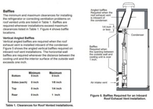 So in a thread on IRV2.com I was talking about my vent problem. One of the things I wanted to do when I removed the refrigerator was to create the vent baffles that were recommended. http://www.irv2.com/forums/f107/what-who-makes-the-correct-vent-cap-for-the-dometic-side-by-side-345404.html#post3657642
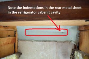
Turns out I cannot do this for a couple of reasons. The evaporator coil is already pressed against the rear or outside shield in the refrigerator cabinet cavity already. So the rear part of the baffle is essentially taken care of.
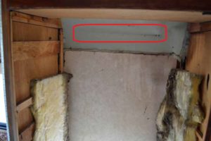
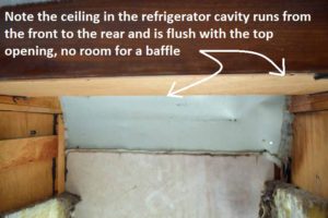
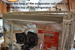
So what about the baffle that should be on the inboard side of the rear vent? Well, there is a problem there as well. The ceiling of the refrigerator cavity runs from the bottom edge of the front of the cabinet to the rear of the cavity. There is a loop in the evaporator tube that extends above the box of the refrigerator. There is essentially no space between the top of the tube and the ceiling in the top of the refrigerator cavity, so I cannot do anything with a baffle in the front either.
In hind sight and after I had put the refrigerator back in the cavity I could have put an extension on top of the refrigerator to close off the area on top of the refrigerator. Hind sight is 20/20.
I could do something on the sides, but they are sealed on both sides. So much for that project.
I will talk about the fans mounted on the rear of the refrigerator later.
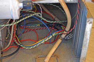
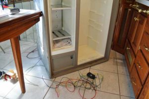
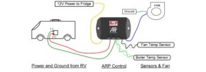 So the wiring of the unit itself is not that complicated. There is a 12 volt wire to the refrigerator to run the refrigerator, a wire to be connected to a 12 volt power supply (the original supply to the refrigerator), two wires 12 volt (negative and positive) for the fans. Then there are two, two wire sensors that need to be placed. On the practical side, this creates quite a rat’s nest, if you do not route and wire tie each wire as you go.
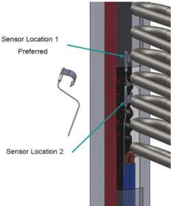
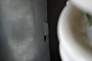
The first step in the install is to attach the RTD sensor to the boiler tube. The instructions state to mount the sensor a least 1” above the electric heating elements, preferably 2” to 5”. The maximum sensor height is below the 2nd from the top absorber coil. The figure supplied says the preferred location is the high one. This means it cannot be done through the heater element access door and the refrigerator must be removed to access this location.
Note I have a Dometic which has the left hand boiler, so we put it where they preferred.
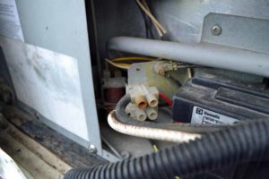
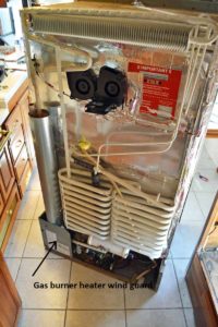 So let’s back up a bit, and take a look at the back of the cooling unit. The heater element access door is not visible until the gas burner wind guard is removed at the bottom of the cooling unit.
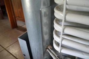 Once the wind guard is removed you can see heater element access door. The tab has to be unbent and the door pushed up before it can be removed.
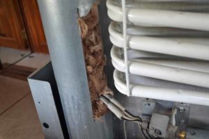
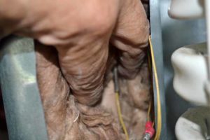
There really is no way to attach the sensor through this door and get it into the preferred location. Even if you could, there just is no room to do it correctly. I decided to remove the entire chimney shield and all the insulation. The instructions state “Repack the insulation into the boiler. Pack extra insulation around the sensor and between the sensor and any heat sources such as the flue tube and electric heaters”.
I also wrapped insulation around the wires to keep them from being worn where the wires come through the seam in the chimney shield. It cannot be seen as the seam faces the back of the refrigerator.
Note! now is an excellent time to replace the heater elements as the access to them is excellent (and they are not that expensive, I did do this).
Now they want you to choose a mounting location for the controller. They say you can mount it pretty much anywhere from outside on top of the refrigerator control module box to inside the RV.
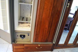
The instructions in the manual state “If you choose the interior, we will add extended wires for a fee. Contact us before purchase”. I elected to mount it inside the RV inside the lower section of the refrigerator, next to the “Climate Control Switch”. This section of the inside of the refrigerator is not cooled and will be at ambient temperature.
To do this, I had to extend all the wires so that they would reach the various components.
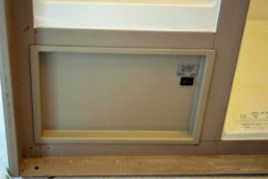 This is the elected position
 Here is the unit with extended wires; I used all the same color wires so the wire color codes could still be followed
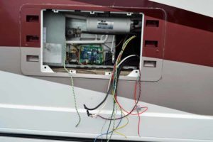
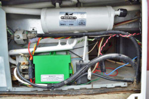
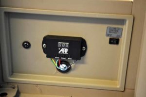 This is the unit mounted with the wires routed through and under the refrigerator. Also mounted is the “optional” circuit breaker. I made the hole large enough for the weather pack connectors I used to connect the control unit to the external components could pass through the hole. I will plug the hole with some insulation.
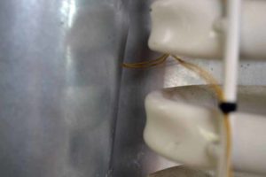
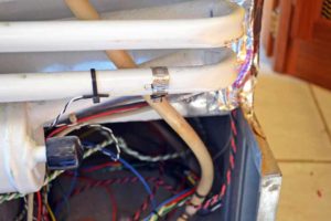
I opted for the ARP v3.1 unit which included two external fans to help with ventilation. So the next thing to be mounted was the sensor for the fans. The figure that shows the suggested location of the sensor does not have the absorber coils shown, but the instructions state “Fig.19 shows the location on the cooling unit to install the fan sensor. The fan sensor can be installed on either the bottom or 2nd from the bottom absorber coil. The sensor can be clamped to the absorber coil with a typical hose clamp” (the clamp was not supplied). After rereading this I may have to go back and relocate the sensor.
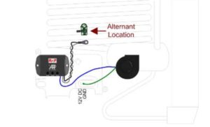
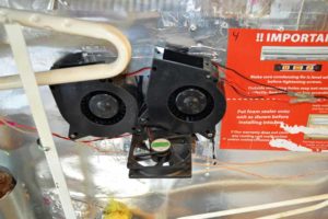
Somewhere I had a discussion on location of the fans. This unit suggests one fan at the side intake and another at the top in the vent pointing out.
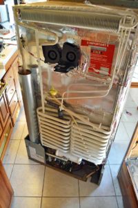
I have talked with JC Refrigeration where the cooling unit was purchased and they state the best place to mount the fans is under the evaporator coil pointing up through the coil.
This was another reason I elected to pull the refrigerator out of the cabinet again.
I actually have their fan kit mounted in that location.
When they built the unit they embed a sheet of sheet metal in the back of the cooling unit so you can screw sheet metal screws into it to mount their fan.
If they went through the trouble of embedding the sheet metal in this location they must believe that this is the spot to mount the fan.
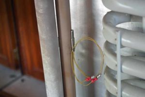
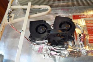
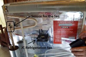 This is how the JC Refrigeration fan kit looks when mounted to the rear. It is switched on and off by a sensor mounted to the end of the evaporator coil on a mount that JC Refrigeration puts on the coil.
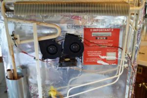
So, if one fan is good then three must be better. I decided to keep the JC Refrigeration fan and add the two fans that came with the ARP unit. I tilted them so they would hit different areas of the evaporator coil (also that is the only way I could get all the screws to hit the sheet metal.
 Now with all the components mounted, it is time to put the refrigerator back into its place
 I used the same color wires on all my extensions that were on the original components. I twisted together the wires from each separate component (Boiler Temperature sensor, fans, fan temperature sensor, etc.)
They were all connected with weather pack connectors so that they can be removed separately. The result is still not as original looking as I would like, but I fear is the best it will be.