| Well here is a project that I have been wanted to do since I took the aftermarket steering stabilizer off. The steering has been fine with no problems, but it was just one more original part that I could put back on the Jeep. |
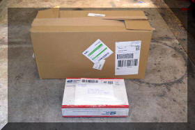
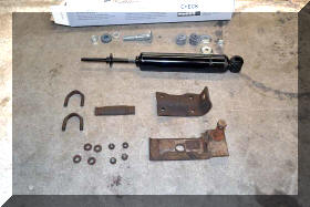
| The first step was to find a stabilizer shock that was configured like the original stablizer shock was. There were a number of posts that said there were none, and a number of inventive ideas on how to create a loop instead of a hole for the end of the shock to mount to, including gate post eye bolts. It turns out there are a number of manufactures that make the correct shock, I went with Monroe, part number SC2940 which turns out to be a Tenneco Steering Stabilizer shock. While I was searching for that I found and original stabilizer setup on Fee-Bay listed by, and I will use his own words, “from a shady overpriced fleabay vender today” who turns out to be one of our own MoC |
 |
 |
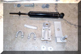 |
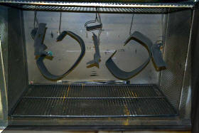
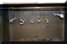
I had an number of the original stabilizer brackets but did not have the small backing plate that goes around the tie rod, you don’t need it , but I’m a nut so I had to have it. First step was to clean everything up. (glass bead, powder coat, and of course two different colors with clear) |
 |
 |
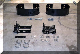 |
So while I was at it I cleaned up the brackets I had along with a set of aftermarket bumperets I ended up with, anyone want so extra parts? |
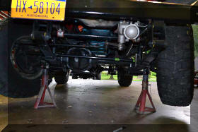
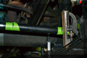
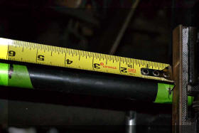
| So on to the Jeep install, first step was to find the center of travel of the tie rod, turned out the total travel was 5 and 7/8 inches, so the center was 2 and 15/16 inches. This is good as the total travel of the shock is 6 and 3/4 which means the shock does not limit the steering radius |
 |
 |
 |
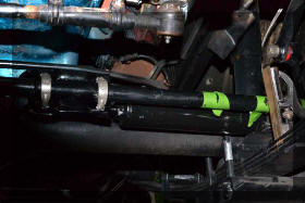 |
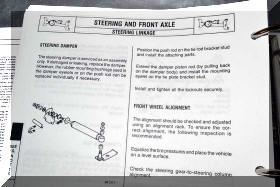
| Now on to the setup of the stabilizer, using the restoration bible the correct configuration was found and a mockup was done. |
 |
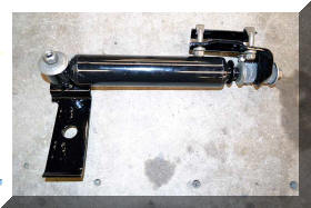 |
| So, everything done by the book, All parts (brackets) are original stock parts, everything mocked up, so everything should fit, correct, wrong! |
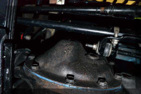 |
In a full right turn the tie rod to stabilizer bracket hits the differential (spindles are stock as are the spindle arms) Tie rod is a Moog part, but that should not make a difference as the location holes in the spindle arms have not been changed. I’m not sure how to fix this. |
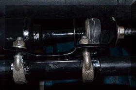 |
In a full left turn the ends of the bolts hit the stabilizer shock, I can gain some clearance by grinding the ends of the bolt off, and by clocking the stabilizer so that the bolt ends are equally spaced around the stabilizer, but then it is not parallel with the tie rod. For now I will do a little of all these things. I need your input to get this correct. |
 |
Turning the bracket from the tie rod to the stabilizer around on the tie rod does not solve the problem because now it hits the differential cover.This is a disappointing end to to days work as now I’m going to pull it all off. |
| Well I really hate giving up so I went back and made som modifications |
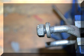 |
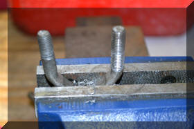
The nuts were hitting th shocl because they were sapced out away from the bracket by a heavey spacer and the spacer was required because the shaft of the u-bolt was not threaded all the way down, so….. |
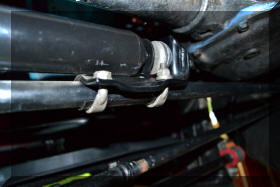
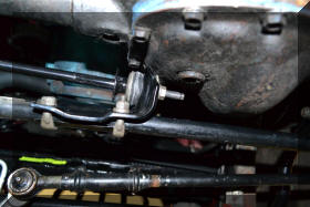
| I threaded the shaft all the way down, now without the spacer and the shaft trimmed off, they no longer hit the body of the shock, maybe the Moog tie rod is a little thicker than stock tie rod and the body of the shock has a bigger diameter than the original shock which caused the problem. The picture makes it look like the bracket is touching the body of the shock, but it is not. |
 |
 |
 |
To fix the problem with the bracket hitting the differential what I did was turn the wheel all the way to the left (up against the spindle stop) and than move the shock to within a 1/16 of bottoming out, and clamp everything down, now when I turn to the right up against the right spindle stop the bracket does not hit the differential. I know the shock is not centered in it’s travel, but it is not bottoming out either |
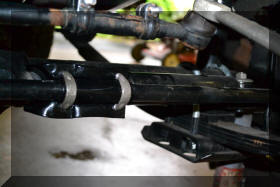 |
Now everything is nice and level and parallel. Now after all this work it is time to take it for a ride and see if I shot myself in the foot or made it better, want take a guess? |
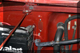
| When I removed the computer it left a hole where the wiring harness came through the fire wall. In addition I misplaced the cover below the heater when i did the upgrade so it is time to make some covers and fill those holes |
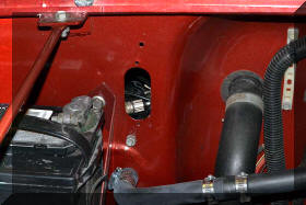 |
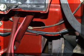 |
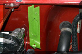 |
The best way I have found to make a pattern is it use masking tape, draw want you need, remove it and stick it to the metal you want to cut out in the form of that pattern.A test fit is then required. |
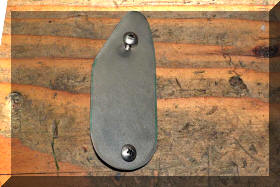 |
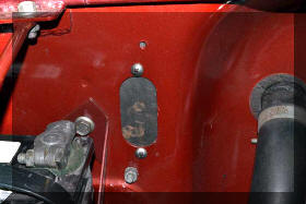 |
| I love powder coat. It is the best form of protection, put it on, cure it for an hour, let it cool and you are done, unlike paint where it can take enamel 7 days to fully cure |
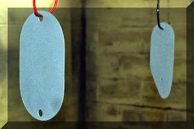 |
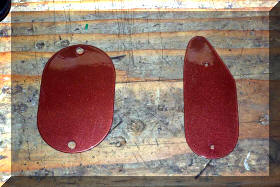 |
| A little red sealer and wipe it clean and all done and sealed. The Powder is a better match than what the picture represents. I took this with a flash, with normal light you can not tell the different between the powder and the paint. |
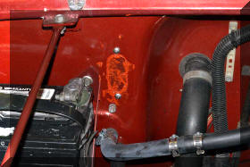 |
 |